


Well here is my latest project. I wanted a way to get to grips simply with the I2C bus on the Raspberry PI. So as I have a problem in setting up my weather station anemometer, to point it north, using a I2C compass (HMC6352) mounted in the anemometer was the answer, which of course is totally over the top solution, great.. roll on.
The mast comes down about twice a year for maintenance, just really to check it over, but every time I put it back up it is a pain to get it to point north, this solves it, well I hope so, it's yet to be fitted, the compass is not the mast :-)
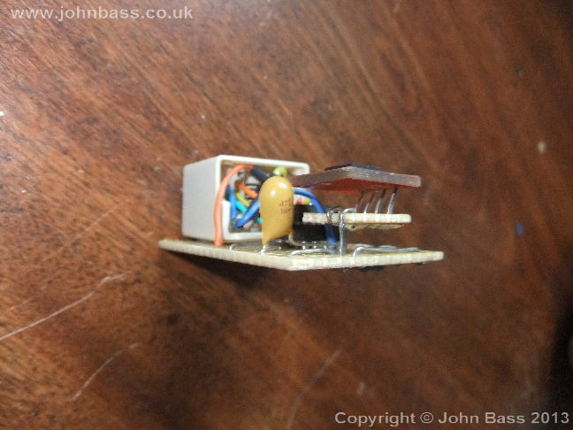
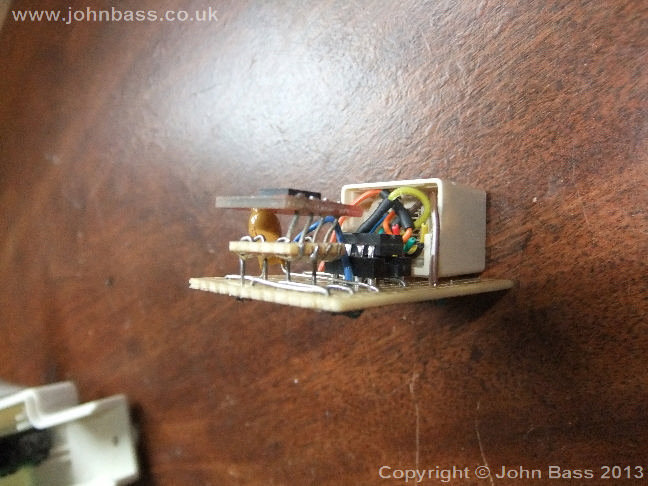
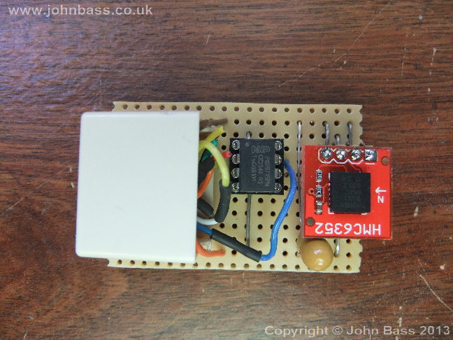
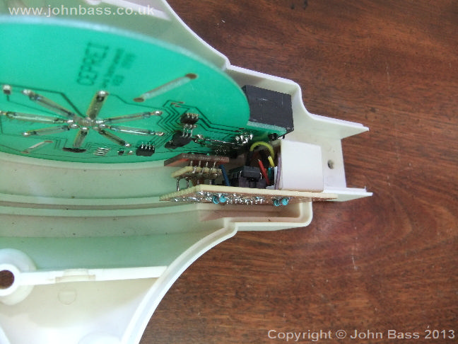
Below you can see the sensor that is going into the anemometer, luckily there is space, in fact AAG must have known I was going to develop this :-), it just fits, perfectly, however it has to be compact, I think I have achieved this....
 |
 |
 |
 |
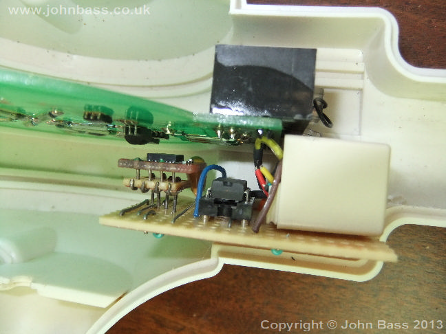
There is one tiny little problem though, the I2C bus was designed to have a max distance of a few inches, not 20 meters plus... However you will notice a little 8 legged chip on the vero board, this is an I2C bus driver (P82B715PN), and it works a treat, so far I have tested it over a 20 meter cat5 patch cable, and it works great. I did however have too pop a small capacitor to help with the power requirements over this length of cable.
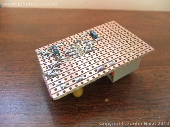
My usual way of making sensors/device easy to remove is to use a good old RJ45 connector, I use RJ45 couplers, that I crack open, a simple twist, even more convenient is the pin assemblies can be removed, thus make them easy to cable. The coupler housing is simply hot glued to the vero board.
 |
 |
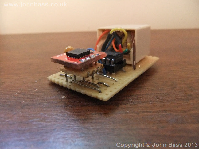
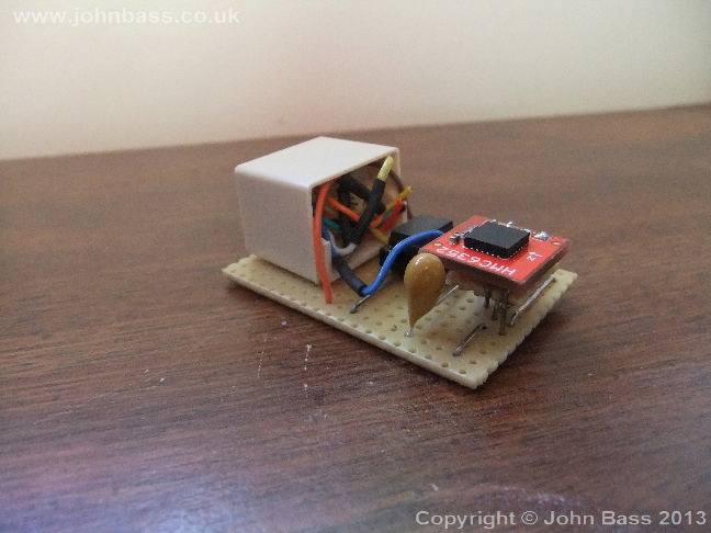
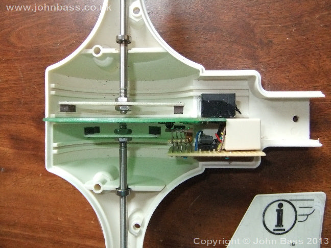
This is the first fit into my backup anemometer, as you will see the compass chip is a tad tight to the main instrument board, so a little fettling was needed..
 |
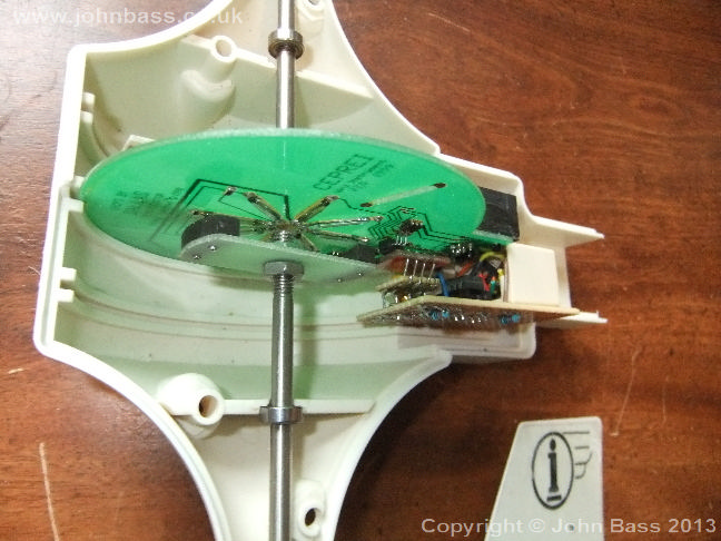 |
Following is the pictures of the fettling, as you can see the distance from the instrument board is much improved.
 |
 |
There is plenty of information on the net about the Raspberry PI and how to setup its I2C bus, and also examples of various code, be it mostly python, which I am just coming round to like, after many years.
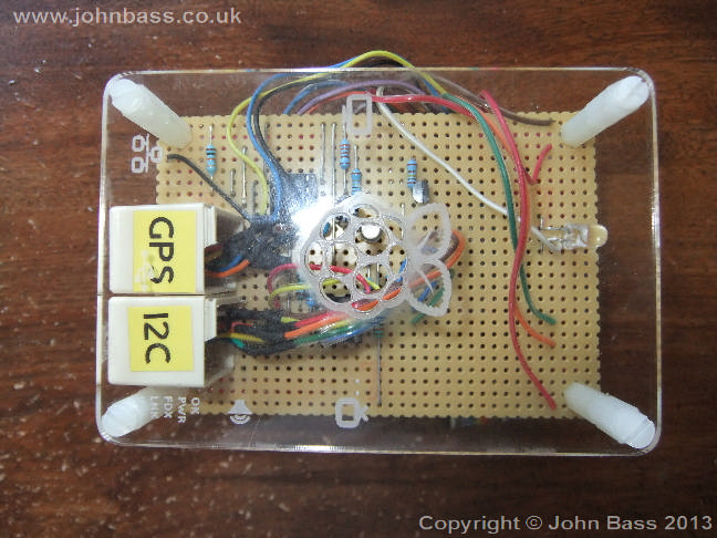
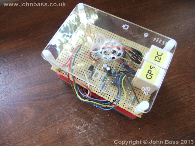
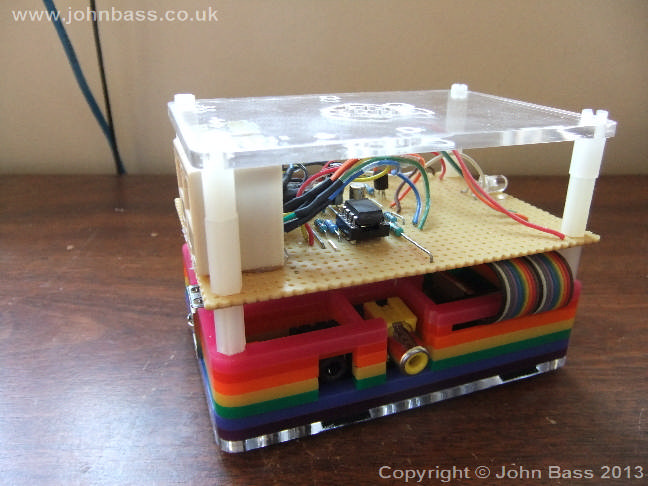
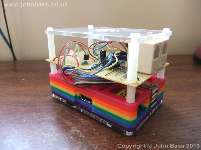
I have also had to modify the Raspberry PI proto vero board, picture to follow, again, it has an RJ45 socket on it, to make it easy to disconnect the compass.
Here are some shots of the circuit at the PI end.
 |
 |
 |
 |