


I decided to build a new Lighting Radar aerial, the last one succumbed to the wood rotting. It was only meant to be temporary.
Well in fact due the original project stalling, sadly the developer passed away, and will be sorely missed. I have found another project on the same lines, so I made the decision to move on to it.
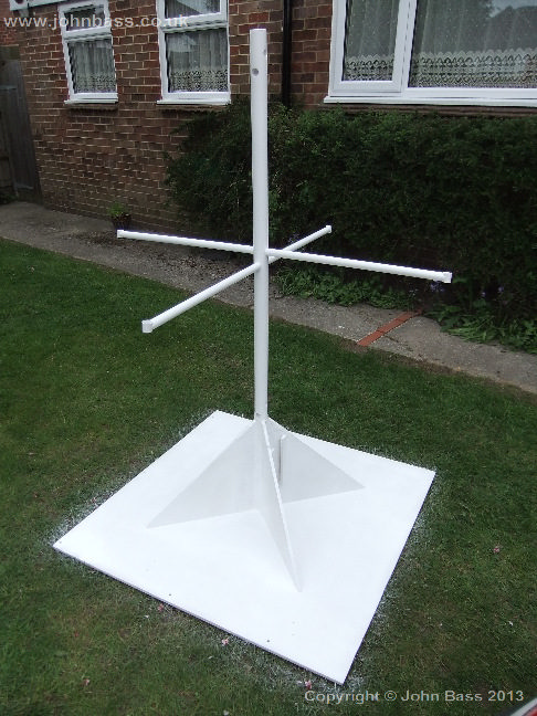
The first issue was I needed a replacement aerial, not this time made from wood.
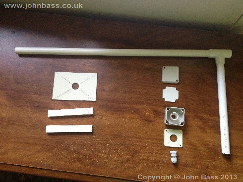
I came up with a very simple solution to solve the problem. Make it out of plastic!, all the parts are quite easy to get hold of, mainly waste pipe, 40mm and 20mm plus a some 10mm plastic sheet! So to the new
 |
 |
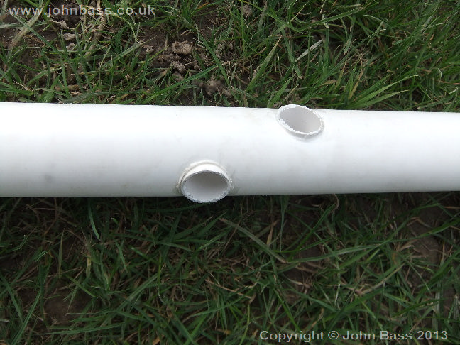
I used a 40mm waste pipe for the main upright. I drilled 6 holes to allow the two windings and spacing tubes to be fitted.
 |
 |
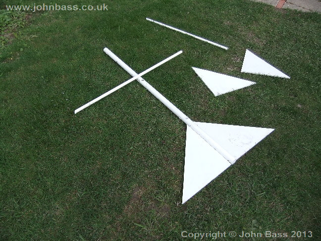
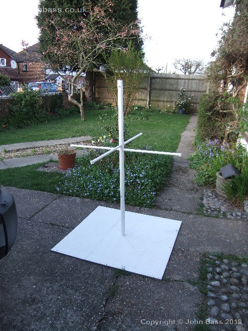
Here is the main parts of the antenna, plus a dry run of the fitting of the spacing rods.
 |
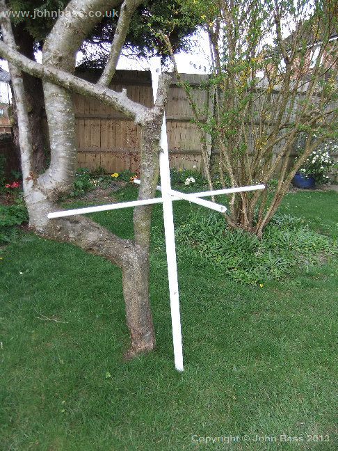 |
Starting to look good.
 |
 |
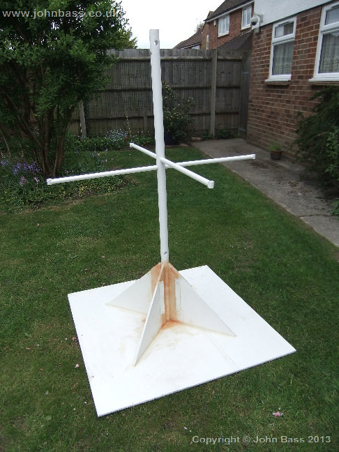
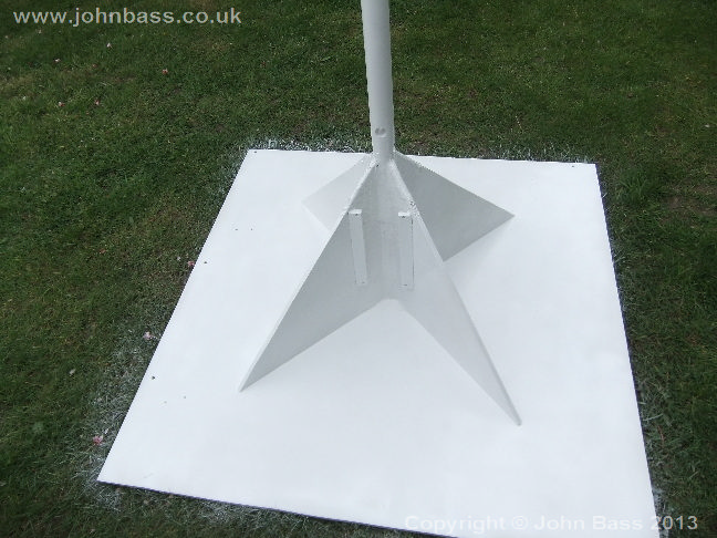
After finding that the fillets were not ad-hearing to the main poll that well, I decided on fibre-glassing them. That did the trick, not the most pretty solution, but certianly very strong. You can also see from the two following pictures the two short uprights to mount the pre-amp housing on to.
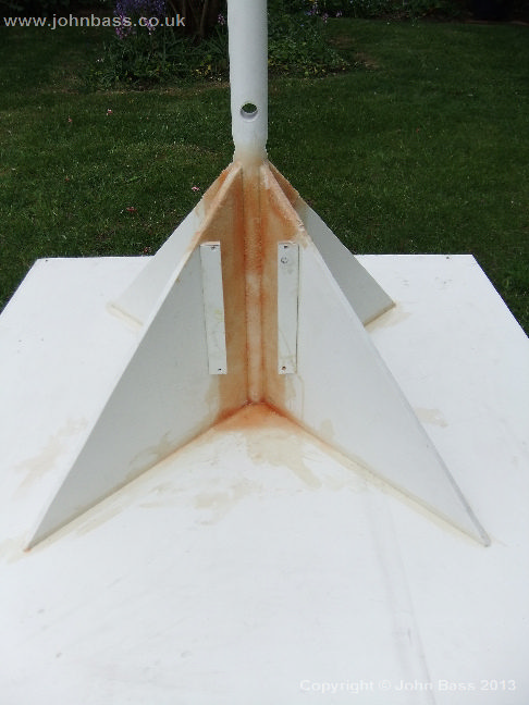
Here is a picture of the fillets fitted.
I also have found an issue where the top of the centre tube is a little too flexible, so I filled the tube with a resin, this worked very well, without add a lot of weight. All this was very messy, which is an understatement. I'm not the worlds best fibre glasser!, but I got there, this made a real difference. It does not look pretty but does the trick.
 |
 |
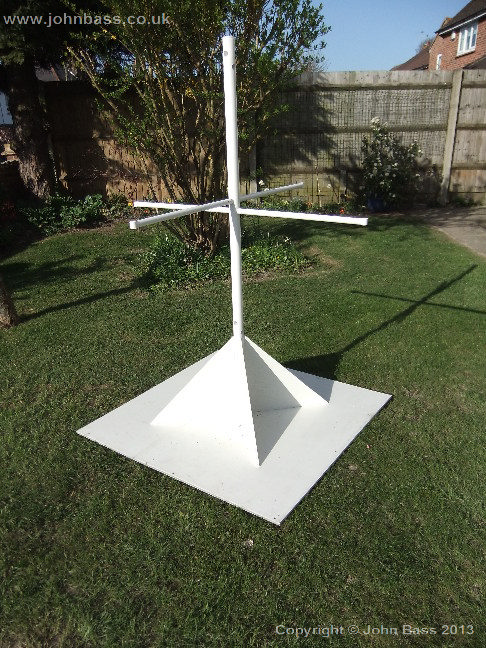
Then for a coat on paint, well about three, this was mainly put on to protect all the plastics from the Sun's UV radiation
 |
 |
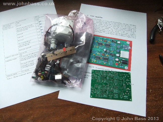
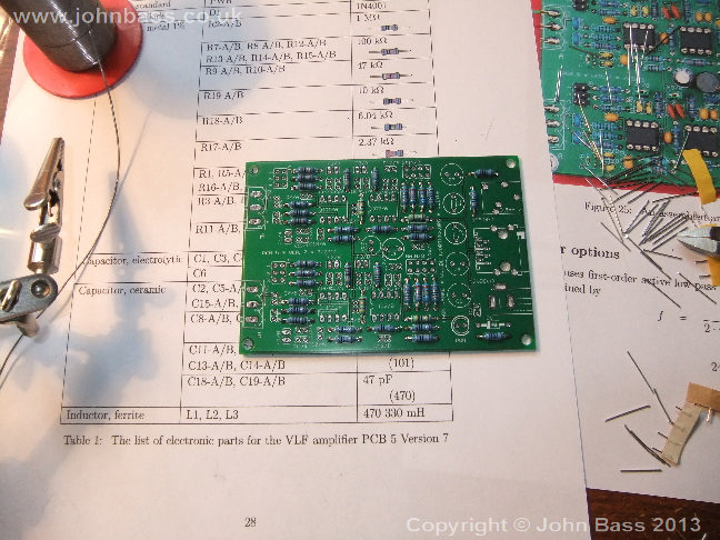
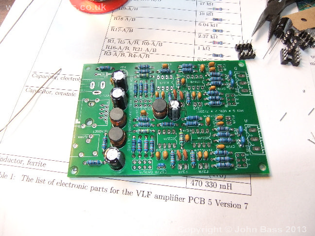
Following is the start of the pre-amp build, quite simple, and easy to understand instructions. Resistors
 |
 |
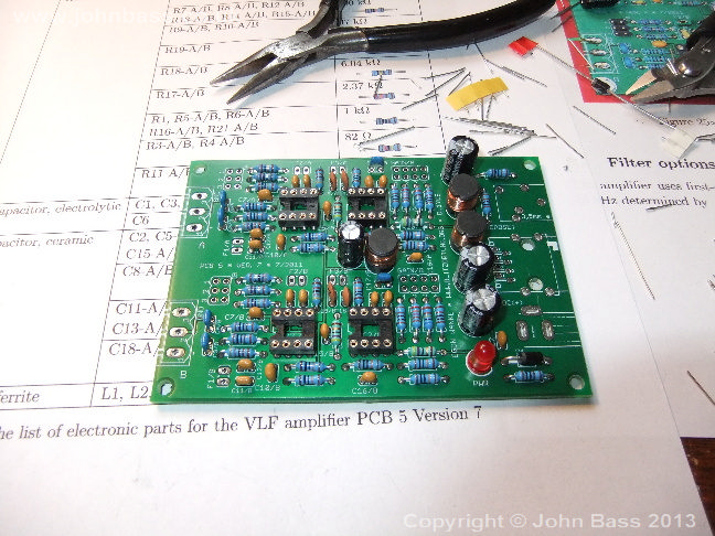
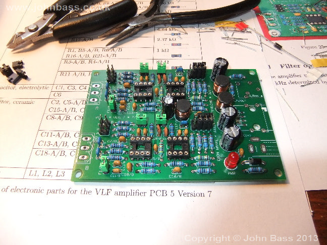
Capacitors and Inductors, IC sockets Leds...
 |
 |
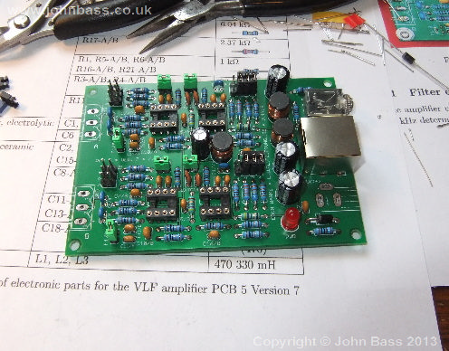
Configuration links, and RJ45 socket.
 |
 |
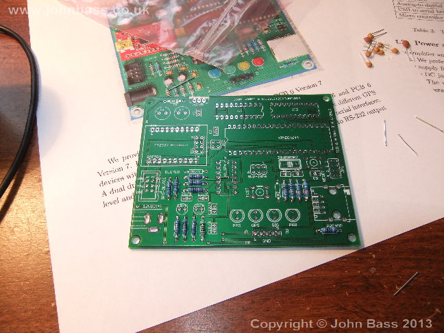
Now on to the controller, this was even more simple. Resistors
 |
 |
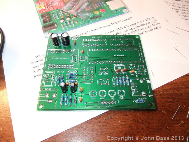
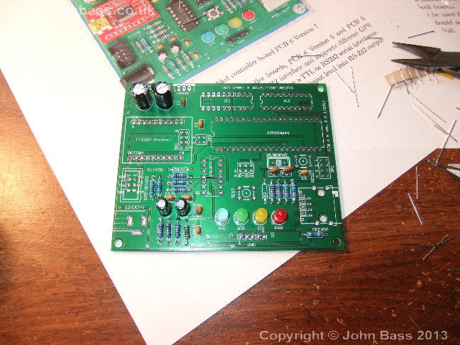
Capacitors and Leds
 |
 |
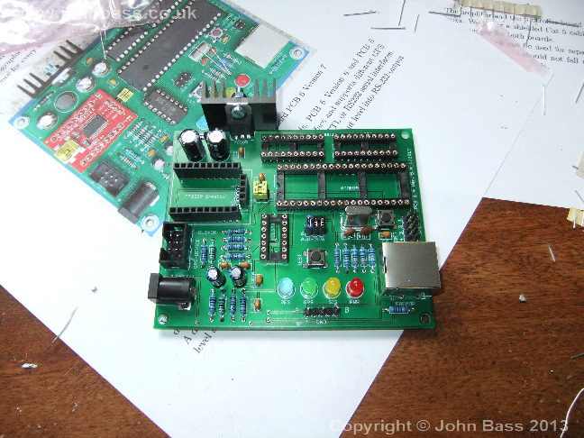
Lastly the Sockets, Regulator and RJ45, done...
 |
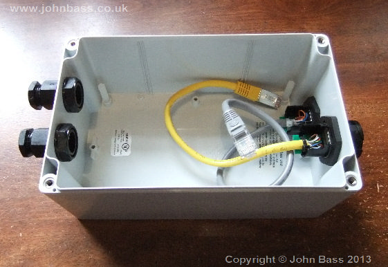
The following show the build of the pre-amp housing. The two glands on the left are for the antenna windings to come into the housing through. The two sockets on the right of the box are for the signal/power cable, this is the yellow one, and the other is for the 1wire sensor/s. I have fitted a temperature and humidity sensor on the housing, see the second picture, this allows me to keep an eye on the state of the housing/amp. I also put some silica gel in the housing to make sure it starts off dry. If any moisture gets in then the humidity sensor should indicate this. This problem afflicted the last radar I built, so this time I thought I would keep my eye on it.
 |
 |
Here you can see the pre-amp and the humidity sensor boards mounted, You may notice I also built a false floor, which is set, just about the 1wire RJ45. With out this it would be difficult to get both boards in the hosing. The second picture shows the pre-amp mounted on the antenna frame.
The incoming windings were not only sealed by the glands, sounds painful, but also siliconed in just to make sure a 100% seal.
| |
|
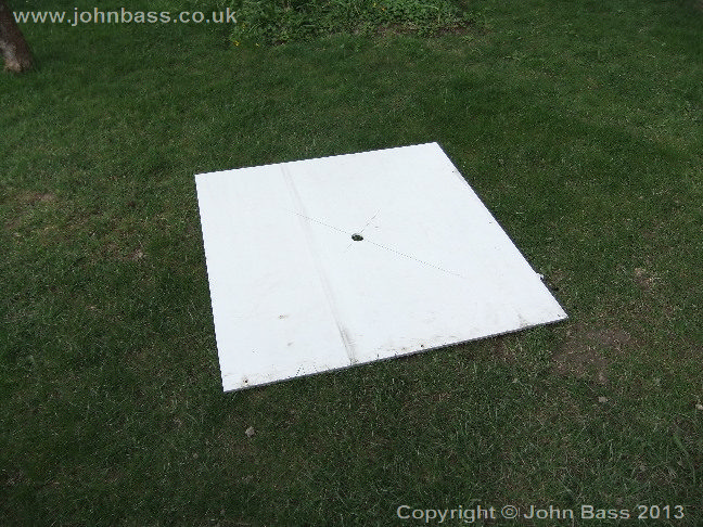
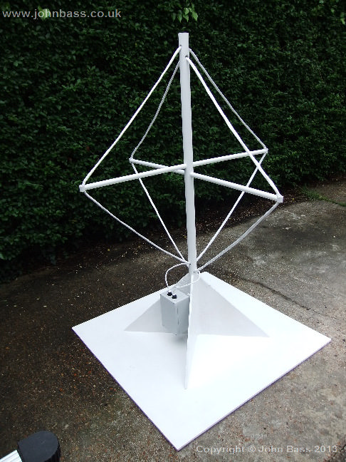
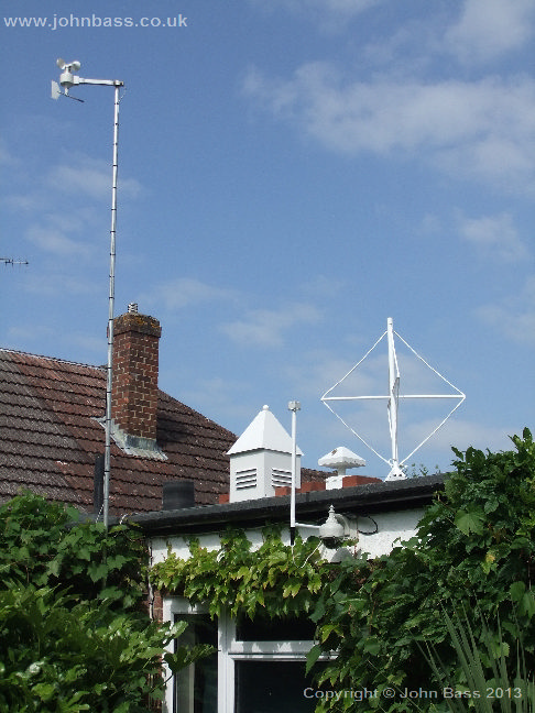
Below is the finished antenna. To get the antenna on the flat roof was interesting, it's not that it's heavy but cumbersome, the base is 1m x 1m. All you need is a tall son, job done.
 |
 |
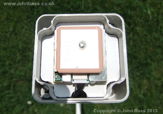
Now on the GPS housing build. I did try putting the GPS receiver next to a window, but that did not really work very well, so on to an external mounting. I looked around for external GPS housings, but nothing was found. So on to building my own.
In the kit was also supplied a small case and gland, so these seemed ok to be used outside, so off we went.
 |
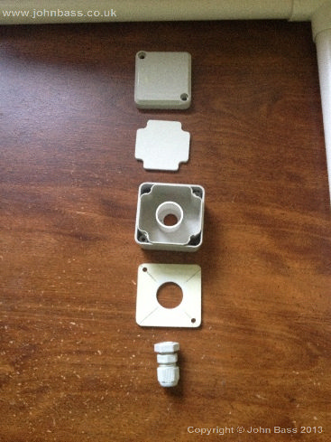 |
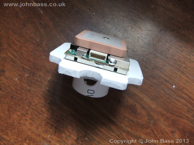
I mounted the EM-406a on the platform just using double sided tape. The reason for the platform was for clearance of the gland and cabling. There is also a 1wire temperature in the housing, so space was also needed for it, without being in the way of the GPS receiver.
 |
 |
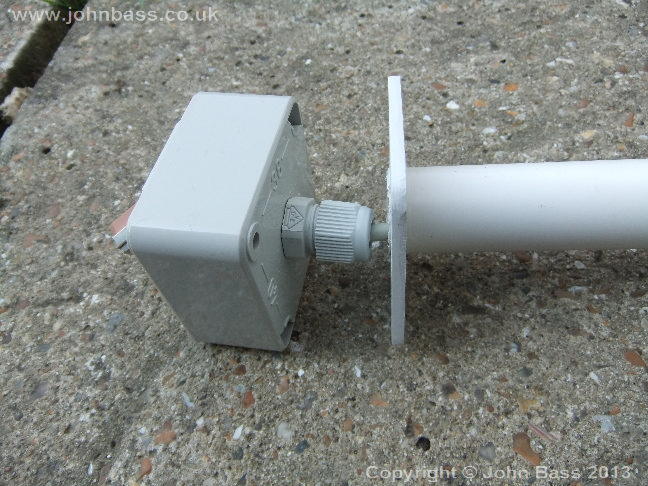
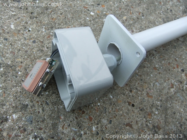
Below you can see the way the GPS housing is affixed to the mounting poll.
 |
 |
This gives a better idea of hight of the stand-off board in the housing.
 |
 |
The picture on the left is the Modified RJ45 connector for the GPS and 1wire. 6 wires are needed for the GPS and two for 1wire, so a result Cat5 and RJ45 connectors are ideal.
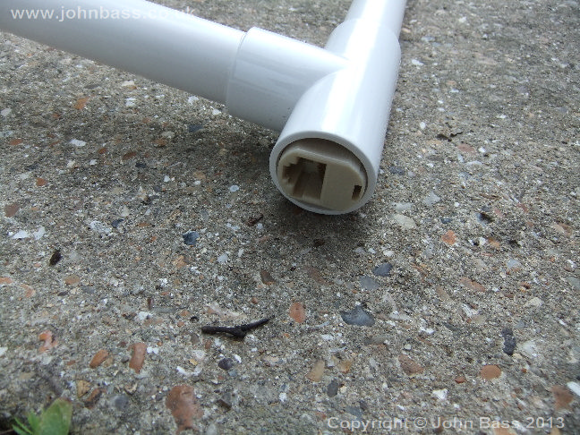
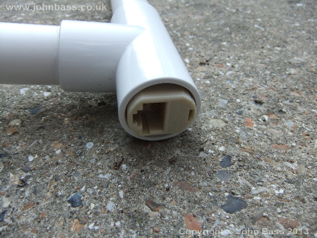
The RJ45 socket is half a RJ45 coupler, with it's corners filled off so it fits in the 20mm tube.
The picture on the right shows the wiring to the GPS and also the 1wire sensor.
 |
 |
Here is the modified RJ45 coupler fitted to the mounting poll, once mounted a plastic boot is put over plug and socket to protect them from the elements.
 |
 |
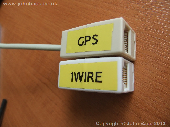
As I was bringing both GPS and 1wire signals down the same Cat5, so I needed to split out the signals to send them to different end points.
The left picture shows the modifications to the RJ45 couplers and on the right the final assembly. The wire is the incoming cable from the GPS and 1wire sensor.
 |
 |
The left picture is the connection to the 1wire network. As I use 1wire hubs, the 1wire network does not need to continue.
The right picture shows the onward connection to the controller and also the blocking of the unused RJ45 socket, the simple use of hot glue did this very well.
 |
 |
Here is the finial install.. done and working. I was very pleased with the final out come, lets just hope it does not fall apart like the wood version...
 |
 |